The Radio Line of Sight (LOS) calculator is a valuable tool that helps determine the maximum distance between two points for effective communication.
This article provides an easy to use calculator with examples, background information, formulas, applications, and limitations of line of sight calculators.
Table of Contents
Calculator
Enter the height of the antenna in either meters or feet.
Background
A radio line of sight (LOS) calculator is commonly used in RF, wireless and telecommunications engineering design and planning.
In telecommunications, for example, LOS calculations are utilized for planning the placement of communication towers or antennas. A clear line of sight is often necessary for optimal signal transmission between two points.
The LOS calculator typically takes into account the Earth’s curvature, terrain, and any obstacles (such as buildings, mountains, or vegetation) that may obstruct the direct line of sight. Engineers and planners use these calculators to ensure that communication links or surveying measurements have a clear and unobstructed view between the specified locations.
Example Calculation
For an antenna that is 50 feet above the ground, the LOS range is 14 km (8.7 miles) and the max service range is 16 km (10 miles). Increasing the antenna height will increase the LOS range.
How is the Line of Sight Calculated?
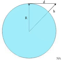
Referring to the picture below

- d = Line of Sight Distance
- h = Antenna Height
- R = Radius of the Earth
Using Pythagorean Theorem
(R+h)2 = d2 + R2
d2 = (R+h)2 – R2 = 2*R*h + h2
since h is small relative to R, d can be approximated as
d = √(2*R*h)
The Radius of the Earth is 6370 km and therefore
d = √(2*6370*h*0.001)
d = 3.57*√(h)
where h is specified in meters and d is in km.
Atmospheric Effect on the Radio Horizon Calculation
The common consequence of the atmospheric pressure decreasing with height (vertical pressure variation) is the refraction or bending of radio waves toward the Earth’s surface.
This phenomenon leads to the creation of an effective Earth radius, typically augmented by a factor of approximately 4/3. This augmentation, referred to as the k-factor, reflects an increased effective radius for radio wave propagation.
The maximum service range is therefore
dr = √(2*R*h*(4/3))
dr = 4.12*√(h)
It’s important to note that the k-factor is not static; its average value may fluctuate based on prevailing weather conditions. Factors such as temperature, pressure, and humidity variations in the atmosphere can influence the k-factor, leading to dynamic changes in the bending of radio waves and, consequently, alterations in the effective Earth radius.
The formula above applies in the case of normal weather conditions.
This variability underscores the significance of considering real-time atmospheric conditions when assessing the range and performance of radio communication systems. For instance under certain adverse weather conditions k can be less than 1.
